Hardware Overview
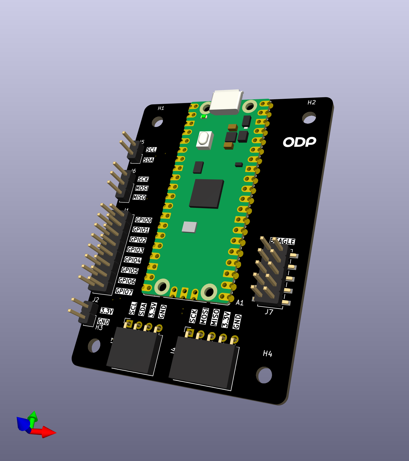 v1.0 — seven pin headers |
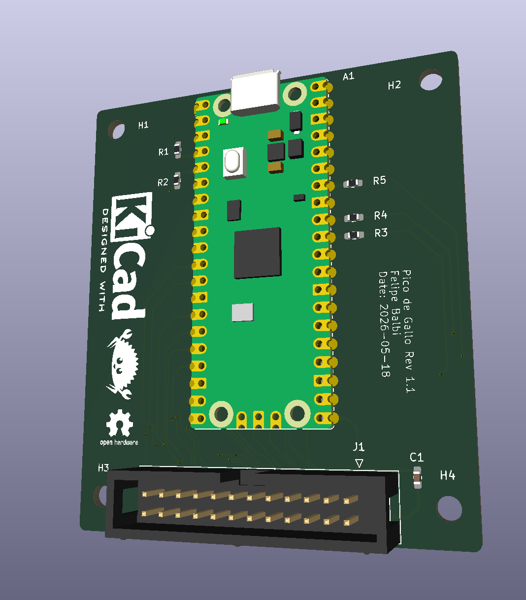 v1.1 — keyed 2×12 box header |
Pico de Gallo is a small landing-board PCB designed to host a Raspberry Pi Pico 2 module via castellated edge pads. The landing board exists for one reason: to make the pin-to-function mapping predictable and labeled, so the firmware always knows where to look for SDA, SCK, UART TX, and friends, and so you don’t have to keep a pinout chart taped to your monitor.
Everything Pico de Gallo can do, a bare Pico 2 with the same firmware can also do — but the landing board adds:
- silkscreened labels for every signal,
- pull-ups for I²C (4.7 kΩ on v1.1+),
- series resistors on ADC inputs (100 Ω on v1.1+),
- decoupling on VREF,
- and a keyed connector so cables only go in one way (v1.1+).
The Pico 2 itself supplies the RP2350 MCU, the USB connector, the BOOTSEL button, and the 3.3 V regulator. Pico de Gallo just brings the right signals to the right places.
Block Diagram
        ┌──────────────────────────────────────────┐
        │              Pico de Gallo PCB           │
        │                                          │
USB ────│──► Pico 2 (RP2350) ──► castellated pads ─┼──► I²C / SPI
        │        │                  │              │      UART / GPIO
        │        │                  │              │      PWM / ADC
        │        │                  │              │      1-Wire
        │        │                  ▼              │
        │        │     pull-ups, series R,         │
        │        │     decoupling, header(s)       │
        │        ▼                                 │
        │  defmt RTT (debug)                       │
        └──────────────────────────────────────────┘
What’s on the PCB
| Component | v1.0 | v1.1+ | Purpose |
|---|---|---|---|
| Pico 2 pads | ✓ | ✓ | Castellated landing for the MCU |
| I²C pull-ups | external | 4.7 kΩ | Required for I²C operation |
| ADC series R | — | 100 Ω | Input protection / RC filter |
| VREF decoupling | — | 100 nF | Stabilises ADC reference |
| Pin headers | 7× | — | Per-bus 0.1″ pin headers |
| Box header | — | 1× 2×12 | Single keyed shrouded connector |
| BOOTSEL button | on Pico | on Pico | Boot to UF2 mass-storage mode |
The Three Ways to Get a Board
- Order a fabricated PCB from any house that accepts gerbers
(JLCPCB, PCBWay, OSH Park, Aisler, …). Our gerbers are on the
Releases
page under
hardware-v*tags. Most houses will also assemble the board if you upload the BOM and pick-and-place files; this is the easiest path and we recommend it. - Hand-solder the Pico 2 and headers yourself. The board has no fine-pitch components — it’s a comfortable first SMT-ish project. See Assembly & Flashing.
- Skip the board entirely and wire a bare Pico 2 directly, matching the pinout in Pinout & Connector. The firmware doesn’t care whether the signals come from a landing board or a breadboard.
What’s Next
- Revisions: v1.0 vs v1.1 — pick the right board for what you want to do.
- Pinout & Connector — every pin, every signal, every revision.
- Assembly & Flashing — get the Pico 2 onto the PCB and the firmware onto the Pico 2.